

Mastering Low-Voltage Earthing Systems: A Detailed Technical Guide for Engineers and Contractors
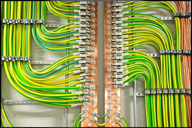
Introduction
Electrical earthing is one of the most important safety elements in any low-voltage (LV) electrical installation. A properly designed earthing system helps protect people from electric shock, provides a controlled path for earth-fault current, and enables protective devices to disconnect faulty circuits within the required time.
For electrical engineers, consultants, contractors, and facility managers, understanding earthing arrangements is essential to designing reliable electrical distribution systems. The selection of an appropriate system influences fault protection, equipment reliability, electromagnetic compatibility, maintenance requirements, and operational continuity.
International standards such as IEC 60364 and national wiring regulations provide frameworks for selecting and implementing suitable earthing arrangements. In India, engineers must also consider applicable Indian Standards, Central Electricity Authority regulations, and relevant state and utility requirements.
This guide explains five principal low-voltage earthing arrangements—TN-C, TN-S, TN-C-S, TT, and IT—with practical examples, calculations, protective-device considerations, and selection guidance.
1. What Is Electrical Earthing?
Electrical earthing is the intentional connection of designated parts of an electrical installation to Earth or to an appropriate protective earthing system.
Its primary objectives are:
- Protection against electric shock: Helps limit dangerous touch voltages on exposed conductive equipment enclosures.
- Fault-current management: Provides a defined path for earth-fault current.
- Automatic disconnection: Enables protective devices to interrupt dangerous faults within the required time.
- Equipotential bonding: Reduces dangerous potential differences between accessible conductive parts.
- Equipment protection: Helps reduce the consequences of insulation failures and electrical faults.
A critical engineering principle is that an earth electrode alone does not guarantee electrical safety. The complete protective arrangement—including protective conductors, bonding, fault-loop impedance, circuit breakers, and residual current devices—must function as a coordinated system.
2. Understanding TN, TT, and IT Classification
Earthing arrangements use standardized letter designations to describe the relationship between the electrical supply, exposed conductive parts, and Earth.
First letter: Relationship between the source and Earth
- T — Terra: One point of the supply, usually the transformer neutral, is directly connected to Earth.
- I — Isolated: Live parts are isolated from Earth, or one point is connected to Earth through an impedance.
Second letter: Relationship between exposed conductive parts and Earth
- T — Terra: Exposed conductive parts are connected to Earth through an installation earth electrode or earthing arrangement.
- N — Neutral: Exposed conductive parts are connected to the earthed point of the electrical supply through a protective conductor.
Additional letters: Arrangement of neutral and protective conductors
- C — Combined: Neutral and protective functions are combined in a single PEN conductor.
- S — Separate: Neutral and protective functions are carried by separate N and PE conductors.
These designations produce the five commonly discussed arrangements.
| Earthing system | Main characteristic |
|---|---|
| TN-C | Neutral and protective functions combined throughout the relevant system |
| TN-S | Neutral and protective conductors remain separate |
| TN-C-S | Combined PEN conductor upstream, separated N and PE downstream |
| TT | Supply is earthed at the source; the installation uses its own earth electrode |
| IT | Source is isolated from Earth or connected through a high impedance |
3. TN Earthing Systems: Metallic Fault-Current Paths
TN systems connect the supply neutral point directly to Earth. Exposed conductive parts are connected to the earthed supply point through a protective conductor.
During a phase-to-earth fault, the intended fault-current path is predominantly metallic rather than through the general mass of soil. This can produce sufficient fault current for an appropriately selected circuit breaker or fuse to disconnect the faulty circuit rapidly.
However, effective protection depends on the measured or calculated earth-fault loop impedance, protective-device characteristics, conductor sizing, and required disconnection time.
3.1 TN-C System: Combined Neutral and Protective Earth
In a TN-C system, a single PEN conductor performs both the neutral and protective earthing functions.
Typical conductor arrangement:
- Three-phase installation: L1, L2, L3 and PEN.
- Single-phase installation: Line and PEN.
Operating principle
Under normal conditions, the PEN conductor carries neutral return current. If a phase conductor contacts an exposed conductive enclosure, the PEN provides a low-impedance return path to the supply source. The resulting fault current is intended to operate the protective device.
Advantages
- Reduced conductor count.
- Potentially lower installation cost.
- Suitable for certain upstream distribution applications where permitted.
Engineering limitations
1. Broken PEN conductor
A broken or disconnected PEN can cause exposed conductive parts to rise to a dangerous voltage. The consequences depend on the network arrangement and connected loads, but the potential shock hazard can be severe.
2. Stray currents and electromagnetic interference
Because normal load current flows through the PEN conductor, unwanted current paths can arise through bonded metalwork and other conductive infrastructure. This can create potential differences and electromagnetic compatibility problems.
3. Residual current protection limitations
RCDs must not be installed in the combined PEN portion of a TN-C system. Where residual current protection is required, the protective and neutral functions must be arranged in a compliant configuration that permits correct RCD operation.
Practical application: TN-C arrangements are generally associated with particular distribution-network applications rather than ordinary final circuits. Their use is subject to applicable regulations and restrictions.
3.2 TN-S System: Separate Neutral and Protective Earth
In a TN-S system, neutral and protective earth are separate conductors throughout the relevant supply and installation arrangement.
Typical conductor arrangement:
- Three-phase installation: L1, L2, L3, N and PE.
- Single-phase installation: Line, N and PE.
Operating principle
During a phase-to-enclosure fault, current returns through the protective conductor toward the earthed supply point. The low-impedance fault loop allows the appropriate overcurrent protective device to disconnect the faulty circuit.
The PE conductor does not normally carry functional load current, although small leakage currents and transient currents can occur.
Advantages
- Clear separation between neutral and protective functions.
- Reduced risk of normal neutral current flowing through protective bonding paths.
- Good electromagnetic compatibility when correctly installed.
- Compatibility with appropriately selected RCDs and RCBOs.
- Straightforward identification and testing of protective conductors.
Engineering considerations
- Additional conductor requirements may increase installation costs.
- Protective conductor continuity must be maintained throughout the installation.
- Fault-loop impedance and disconnection times must be verified.
- Neutral-to-earth connections must not be introduced downstream where prohibited.
Practical application: TN-S arrangements are useful in installations requiring well-defined protective conductor paths, including many commercial and industrial facilities.
3.3 TN-C-S System: Combined Upstream, Separate Downstream
The TN-C-S arrangement combines upstream PEN distribution with separate neutral and protective conductors inside the consumer installation. It is commonly associated with Protective Multiple Earthing (PME) arrangements in networks where the supply authority provides this facility.
Operating principle
The PEN conductor carries both neutral and protective functions in the upstream section. At the designated separation point, the installation's neutral and protective conductors become separate. Downstream of that point, they must remain separate in accordance with applicable installation rules.
Advantages
- Economical distribution infrastructure.
- Separate N and PE conductors within the installation.
- Effective fault-current paths when correctly designed.
- Compatibility with RCD protection downstream of the separation point.
Critical engineering considerations
Broken PEN risk: A failure in the upstream PEN conductor can cause dangerous potential differences between bonded conductive parts and remote Earth.
Main protective bonding: Appropriate bonding of relevant extraneous-conductive-parts is essential. Bonding helps reduce potential differences between accessible conductive parts, but it does not eliminate every hazard associated with a broken PEN.
Installation restrictions: TN-C must not be recreated downstream of the TN-C-S separation point unless a specific arrangement is expressly permitted by applicable rules.
Practical application: TN-C-S is used where the utility provides a compliant PEN-based supply arrangement.
4. TT Earthing System: Independent Installation Earth Electrode
In a TT system, the supply source is earthed, while the consumer's exposed conductive parts are connected to an installation earth electrode. The installation does not rely on a utility-provided metallic protective earth conductor as its primary protective path.
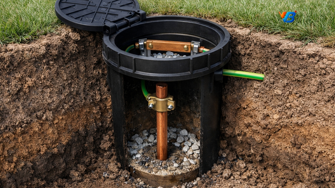
Figure 1: The earth pit installation
4.1 Typical Arrangement
- Line and neutral conductors supply the load.
- The source neutral is earthed at the supply transformer.
- A local earth electrode connects the installation's protective earthing system to Earth.
- Protective conductors connect equipment enclosures to the installation's main earthing terminal.
4.2 Why Earth-Fault Impedance Matters
During a phase-to-enclosure fault, the current returns through the protective conductor, local earth electrode, soil, source earth electrode, and supply transformer.
The total earth-fault loop impedance can be substantially higher than in a TN system. Consequently, earth-fault current may be too low to operate an ordinary MCB or fuse within the required disconnection time.
4.3 Worked Engineering Example
Consider a 230 V single-phase installation with a simplified total earth-fault loop resistance of 20 Ω.
Using Ohm's law:
[ I_f=\frac{U_0}{Z_s} ]
Where:
- (I_f) = prospective earth-fault current.
- (U_0) = nominal voltage to Earth.
- (Z_s) = total earth-fault loop impedance.
Therefore:
[ I_f=\frac{230}{20}=11.5\text{ A} ]
The estimated fault current is 11.5 A.
An ordinary 16 A or 32 A MCB cannot be assumed to disconnect this fault within the required time. Its response depends on the actual current and time-current characteristics of the selected protective device.
This demonstrates why relying on an MCB alone may be inadequate for fault protection in a TT installation.
Engineering note: The example assumes a simplified loop impedance. Actual calculations must include all relevant conductor, electrode, soil, and source impedances.
4.4 RCD Protection in TT Systems
RCDs are commonly essential to achieving fault protection in TT installations because they detect an imbalance between currents in the live conductors and disconnect the circuit when the residual current reaches the device's operating characteristics.
A 30 mA RCD is commonly used for additional protection against electric shock where required. Its actual disconnection time depends on the residual current, device type, and applicable product and installation requirements.
The basic coordination condition is:
[ R_A\times I_{\Delta n}\leq U_L ]
Where:
- (R_A) = resistance of the installation earth electrode and associated protective conductor path, as defined by the applicable standard.
- (I_{\Delta n}) = rated residual operating current of the RCD.
- (U_L) = applicable conventional touch-voltage limit, commonly 50 V AC in ordinary conditions.
For example, if (R_A=100,\Omega) and (I_{\Delta n}=0.03\text{ A}):
[ 100\times0.03=3\text{ V} ]
The calculated product is 3 V, below the conventional 50 V limit. This relationship is a coordination criterion; it does not replace verification of disconnection times, electrode performance, bonding, or other protective requirements.
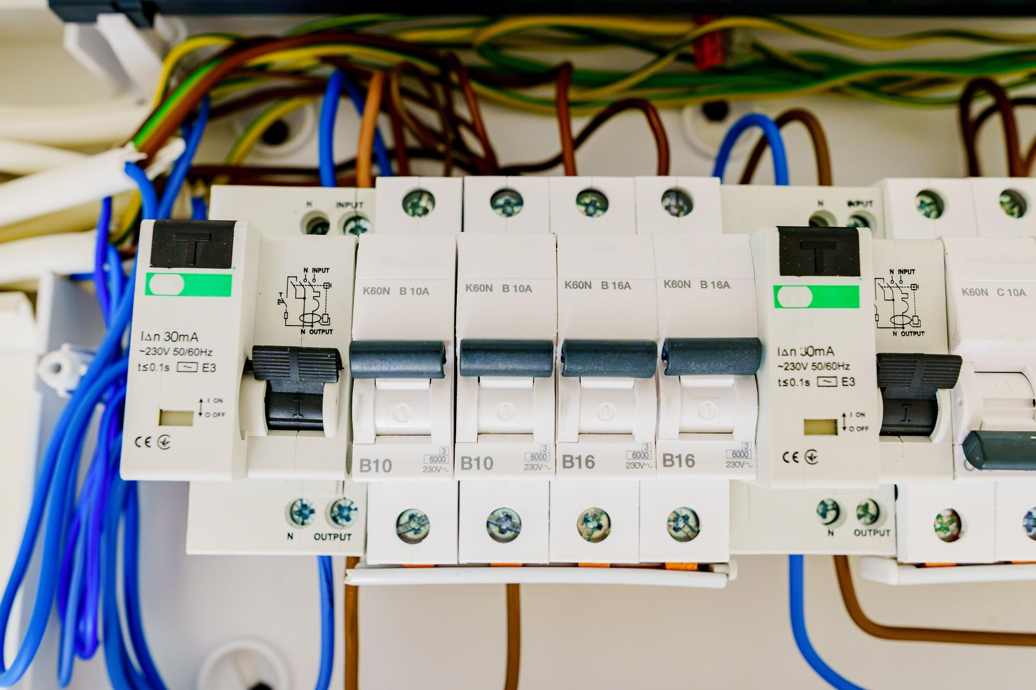
Figure 2: RCD and RCBO devices are selected and tested as part of a coordinated protective system. Confirm device type and performance for the actual loads.
Practical application: TT arrangements are useful where a reliable supply earth is not available to the consumer, including certain rural, temporary, and independent installations.
5. IT Earthing System: Continuity During the First Fault
An IT system is designed for applications where continuity of supply is important and the first insulation fault may be tolerated under controlled conditions.
The source's live conductors are isolated from Earth or connected through a sufficiently high impedance. Exposed conductive parts are connected to an appropriate protective earthing arrangement.
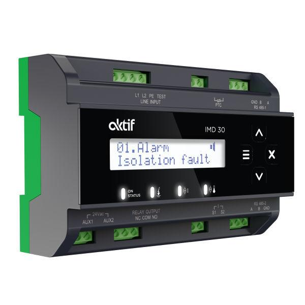
Figure 3: Industrial monitoring panel.
5.1 First-Fault Behaviour
When a single live conductor develops an insulation fault to an earthed enclosure:
- Fault current is limited by the system's insulation impedance, distributed capacitance, and any intentional source impedance.
- The installation may continue operating.
- An insulation monitoring device (IMD) detects deterioration in insulation resistance and provides a warning.
- Maintenance personnel must locate and rectify the fault promptly.
An IT system does not automatically guarantee that touch voltage remains below 50 V under every condition. The result depends on the installation's electrical characteristics and earthing arrangement, which must be assessed during design.
5.2 What Happens During a Second Fault?
A second insulation fault on a different live conductor can establish a dangerous fault-current path.
If the exposed conductive parts are interconnected through protective conductors, the resulting fault may behave like a phase-to-phase short circuit through the protective network. Where the parts are earthed separately or in groups, the fault-current path and required protective measures may differ.
Overcurrent devices or RCDs must provide the required disconnection where the applicable design requires it.
5.3 Typical Applications
IT systems are used in selected applications where continuity is important and specialist monitoring is available, including:
- Medical locations with isolated power systems, where specifically required by medical electrical installation standards.
- Selected industrial processes.
- Certain mining and marine installations.
- Special-purpose electrical distribution systems designed for continuity of service.
Important: IT earthing is not simply an ordinary installation with its neutral disconnected from Earth. It requires a coordinated design, appropriate insulation monitoring, fault-location procedures, and protection against subsequent faults.
6. Comparative Analysis of LV Earthing Systems
The following table summarizes the key differences between TN-C, TN-S, TN-C-S, TT, and IT earthing systems.
| Parameter | TN-C | TN-S | TN-C-S | TT | IT |
|---|---|---|---|---|---|
| Source earthing | Direct | Direct | Direct | Direct | Isolated or impedance-earthed |
| Combined PEN conductor | Throughout relevant system | No | Upstream section | No | No |
| Main fault-current path | Predominantly metallic | Predominantly metallic | Predominantly metallic | Includes Earth and electrodes | Depends on first- or second-fault condition |
| First-fault response | Automatic disconnection | Automatic disconnection | Automatic disconnection | Automatic disconnection, commonly using RCDs | First fault may be tolerated with monitoring |
| Typical protection | Overcurrent devices | Overcurrent devices and, where required, RCDs | Overcurrent devices and, where required, RCDs | Commonly RCD-based | IMD plus coordinated fault protection |
| Main concern | Broken PEN and stray currents | PE continuity and loop impedance | Upstream PEN failure | Electrode impedance and RCD coordination | First-fault detection and second-fault protection |
| Common application | Selected distribution networks | Commercial and industrial installations | Suitable utility-supplied installations | Installations with independent earth electrodes | Selected continuity-critical systems |
Engineering note: The table provides a general comparison. Actual protection requirements depend on the installation design, protective-device characteristics, and applicable electrical standards.
No earthing arrangement is universally superior. The correct choice depends on the source characteristics, utility requirements, load type, environmental conditions, protection strategy, and applicable standards.
7. Essential Engineering Checks Before Commissioning
Selecting an earthing arrangement is only the first step. The completed installation must be inspected, tested, and verified.
7.1 Protective Conductor Continuity
Confirm continuity of protective conductors and required bonding connections. An apparently low earth-electrode resistance cannot compensate for a broken PE conductor.
7.2 Earth-Electrode Resistance
For installations using earth electrodes, measure electrode resistance using an appropriate method and suitable test equipment.
The acceptable value must be established from the earthing design, protective-device characteristics, applicable standards, and supply authority requirements. A single resistance target should not be applied indiscriminately to every installation.
7.3 Earth-Fault Loop Impedance
Measure or verify earth-fault loop impedance to establish whether the selected protective devices can disconnect faults within the required time.
For TN systems, the relationship between prospective fault current and protective-device operation is particularly important.
7.4 RCD and RCBO Testing
Where residual current protection is installed, verify:
- Correct device selection and rating.
- Appropriate RCD type for the connected loads.
- Correct wiring and separation of neutral and protective conductors.
- Operating time and residual-current performance using suitable test equipment.
- Coordination and selectivity where multiple RCDs are installed.
The built-in test button is useful for routine functional checks but does not replace instrument-based commissioning tests.
7.5 Equipotential Bonding
Verify that required bonding connections are correctly sized, securely terminated, and connected to the designated earthing terminal.
Special attention is necessary in TN-C-S installations because of the potential consequences of an upstream PEN failure.
7.6 Insulation Resistance and Functional Verification
Carry out the required insulation resistance tests and other initial verification procedures. In IT systems, confirm the operation of the insulation monitoring device and the procedures for responding to its alarms.
All results should be documented in the installation's test and commissioning records.
8. Common Earthing Design Mistakes to Avoid
Electrical engineers and contractors should pay particular attention to these recurring problems:
- Treating an earth electrode as the complete protection system. Protective conductors, bonding, and automatic disconnection are equally important.
- Assuming a low electrode resistance guarantees a safe installation. The complete fault path and protective-device performance must be assessed.
- Mixing neutral and protective conductors downstream of their designated separation point. This can introduce dangerous current paths and interfere with RCD operation.
- Selecting RCDs without considering the connected equipment. Electronic drives, inverters, UPS systems, and other loads may require particular RCD types.
- Ignoring the broken-PEN hazard. TN-C-S installations require the protective bonding and other measures specified by the applicable rules.
- Failing to test the completed installation. Design calculations must be supported by appropriate inspection and commissioning measurements.
- Using a generic resistance value for every project. Acceptance criteria depend on the selected earthing system and applicable regulations.
9. Which Earthing System Should You Choose?
The selection process should begin with the supply arrangement and the consequences of electrical faults.
- TN-S: Consider where separate protective conductors are available and a clearly defined protective path is desirable.
- TN-C-S: Consider where the utility provides a compliant PEN-based supply and the installation can satisfy the associated bonding and protection requirements.
- TT: Consider where the consumer must provide an independent earth electrode and suitable residual current protection.
- IT: Consider where continuity during a first insulation fault is necessary and insulation monitoring and specialist maintenance can be provided.
- TN-C: Use only where the arrangement is permitted and appropriate for the specific distribution application.
In Kerala, engineers and contractors should verify the actual supply earthing arrangement rather than assuming it from the appearance of the service cable or the presence of a local earth electrode. The design must comply with applicable Indian electrical safety regulations, relevant IS standards, and the requirements of the electricity distribution authority.
10. Applicable Standards and Technical References
The following documents provide useful starting points for detailed design and verification:
- IEC 60364-4-41: Protection against electric shock in low-voltage electrical installations.
- IEC 60364-5-54: Earthing arrangements, protective conductors, and protective bonding conductors.
- IEC 61557-6: Equipment for testing the effectiveness of residual current devices.
- BS 7671: Requirements for Electrical Installations, where applicable to the project.
- Relevant Indian Standards and CEA regulations: Apply the current editions and requirements relevant to the installation and jurisdiction.
Engineers should consult the applicable current editions, amendments, and local requirements before finalizing a design. This article is a technical overview, not a substitute for the governing standards or a project-specific electrical design.
Conclusion
A reliable low-voltage earthing system is much more than an earth rod or a green-and-yellow protective conductor. It is a coordinated arrangement of source earthing, protective conductors, bonding, fault-current paths, and protective devices.
TN-C, TN-S, TN-C-S, TT, and IT systems each serve different engineering purposes. Understanding their operating principles and limitations enables engineers and contractors to make better design decisions, reduce electrical hazards, and improve installation reliability.
For every project, the objective remains the same: provide effective protection against electric shock, ensure faults are detected and disconnected as required, and maintain a safe electrical installation throughout its service life.
Need professional electrical design or earthing-system assessment?
V4 Building Solutions supports electrical design, safety assessments, and technical services for building projects in Kerala. Contact our team to discuss your installation requirements and arrange an assessment appropriate to your project.
Disclaimer: This article is intended for technical education. Electrical installations must be designed, installed, tested, and maintained by competent professionals in accordance with the applicable regulations and standards.